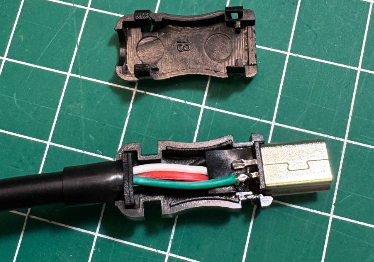
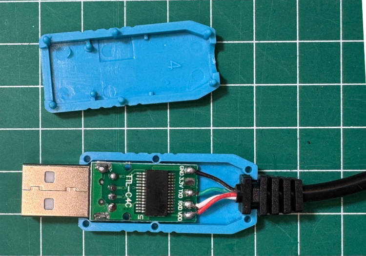
Let me start by saying that this is not a soldering tutorial.
There are plenty of great tutorials online like:
-
Sparkfun has an excellent one: Through-Hole Soldering.
-
And so does Adafruit: Guide To Excellent Soldering.
Everyone has his style for building/soldering things. This is just my way of building/assembling the calculator.
Tips:
-
Take your time and avoid rushing.
-
Ensure all solder joints are secure and well-soldered.
-
All components should sit flush against the PCB.
-
Slightly bending the leads of the parts may help keep them in place.
-
Begin by soldering the shortest components first.
-
Take extra care when installing the buttons, as there is a tight tolerance between the keycaps and the top panel.
-
Follow the sugested order.
-
All components are install on the top side of the PCB.
-
Too much heat can damage the components.
-
Use the top panel as guide when soldering the buttons.
Small Signal Diodes
(1N4148)
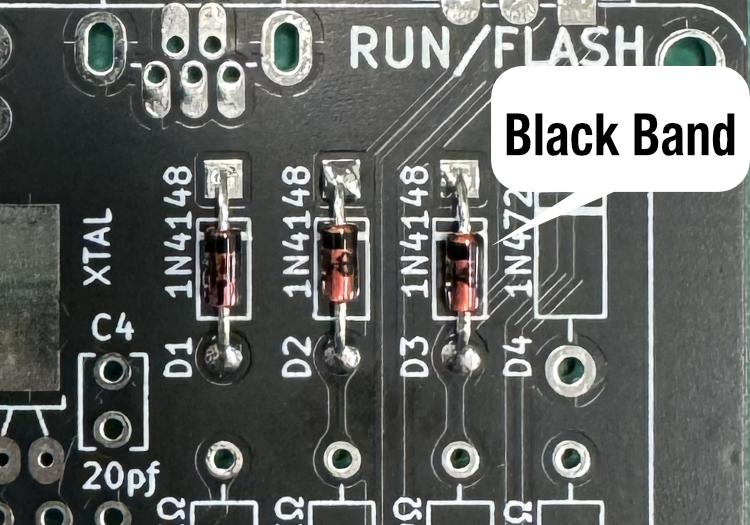
Begin by soldering the three small signal diodes (D1, D2, and D3) as they are the shortest components.
Ensure the diode polarity is correct.
Align the black bands on the diodes with the corresponding markings on the PCB silkscreen.
On newer kits, D2 has been replaced with a Schottky diode (BAT43). You can easily identify it as it is slightly larger than the 1N4148 diodes.
Resistors
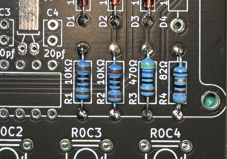
Solder the four resistors (R1, R2, R3 and R4).
Resistor values are clearly labeld on the PCB. Check resistor value with ohm meter to make sure where to place it.
R1: 10KΩ
R2: 10KΩ
R3: 470Ω
R4: 82Ω
Zener Diode
(1N4728)
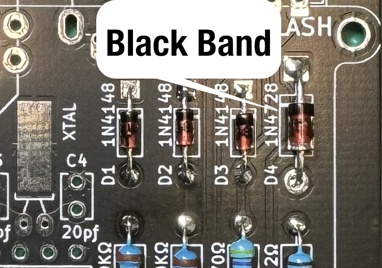
Solder the 3.3V Zener diode.
Ensure the diode polarity is correct.
Align the black bands on the diode with the corresponding markings on the PCB silkscreen.
The zener diode ensure that the voltage from the USB connector never exceeds 3.3V.
Quartz Crystal
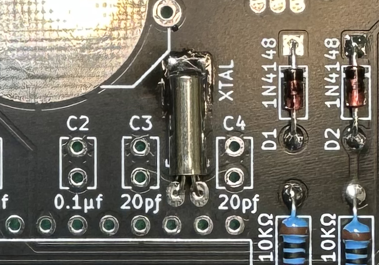
Solder the 32.768kHz clock crystal to the PCB.
It is recommended to also solder the crystal can to the PCB for better stability.
Capacitors C1 and C2
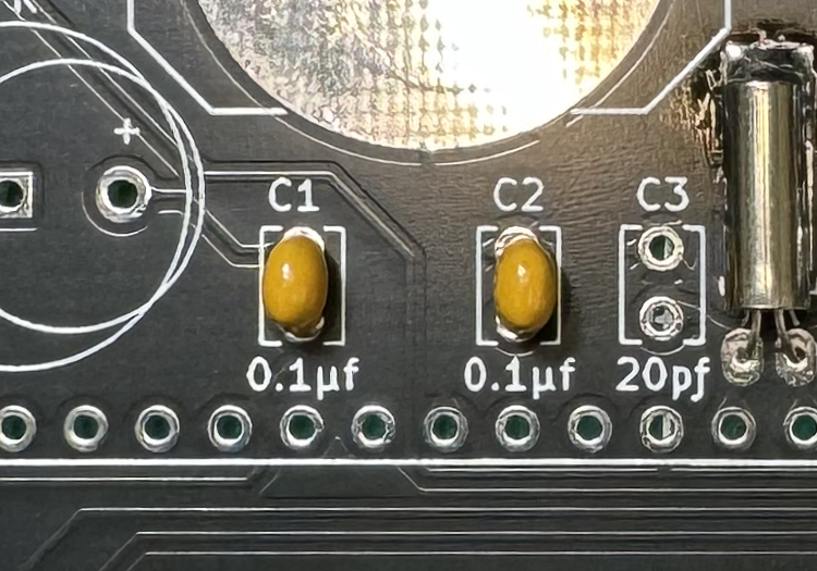
Solder 0.1µf capacitors C1 and C2.
C1 limits the current to the speaker.
C2 is used as decoupling capacitor for the microcontroller.
Capacitors C3 and C4
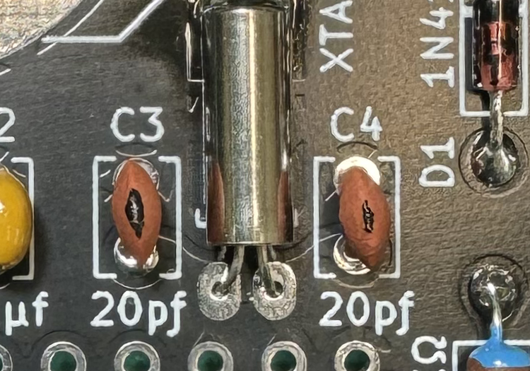
Solder the two 20pƒ capacitors.
They are located next to each side of the crystal.
These load capacitors are used to stabilized and start the crystal.
On newer kits, C3 and C4 have been replaced with 2pƒ capacitors for better timing.
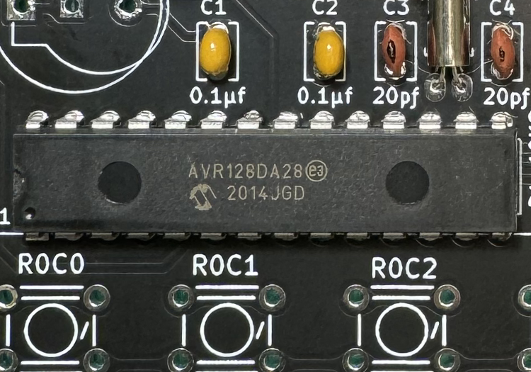
AVR128DA28
Solder the Microcontroller.
Make sure the microcontroller is completely flush against the board.
Align the microcontroller's notch or dot (pin 1) with the pcb markings.
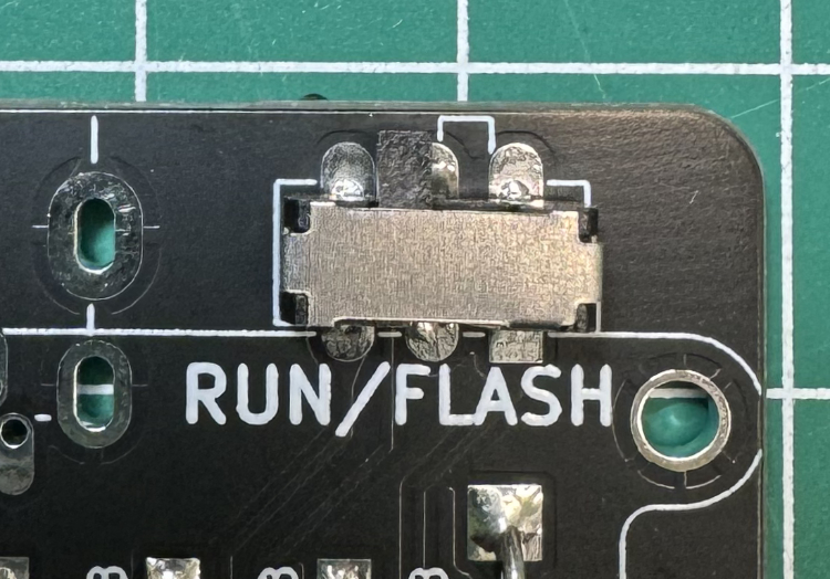
DPDT slide switch
Solder the DPDT slide switch.
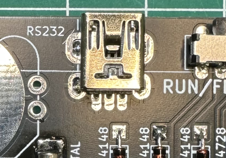
USB Mini
Solder the USB mini female connector.
Please note that the pins of the USB connector barely protrude the PCB.
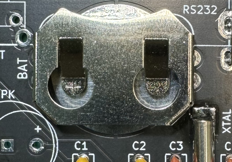
Battery Holder
Solder the CR2032 battery holder.
Please note that this holder can accommodate thinner batteries. Therefore, it is advisable to bend the springs slightly to alleviate the pressure on the CR2032 battery.
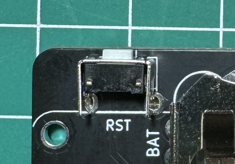
Reset Switch
Solder the Reset Switch.
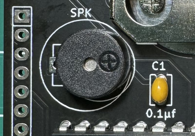
Speaker
Solder the Magnetic Buzzer.
The PCB can accomodiate diferent size of speakers.
Align the + marking on the speaker. Only 2 pins will be used.
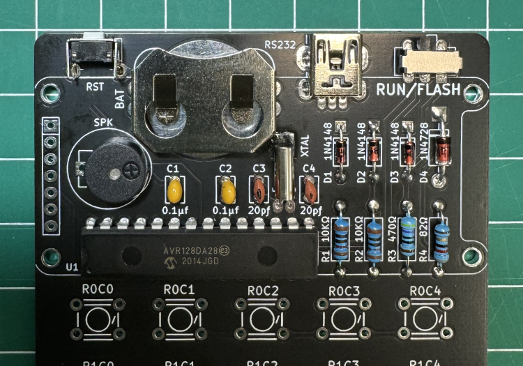
Recap
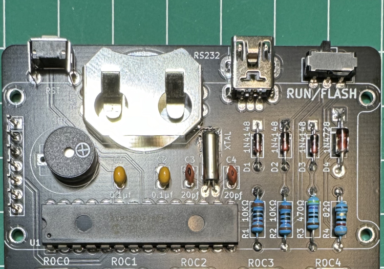
This is how your PCB board should look like.
Now is time to take a break before we continue.
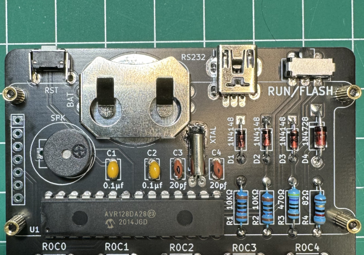
Display Male Header
Soldering the 7 pin male header is a bit tricky.
Start by hand screwing the four 5mm brass posts as shown in the photo.
The display module should sit on top of the brass posts.
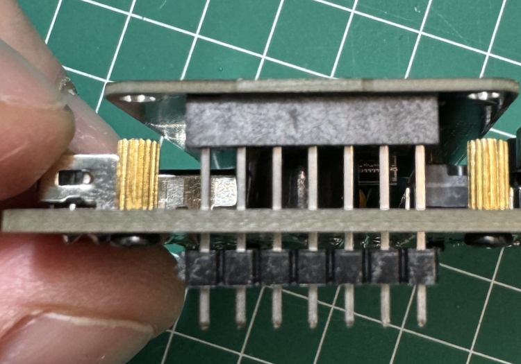
Place the long pins from the male header from the back of the PCB.
And insert the pins on the Display Board.
Make sure the display board is flush to the brass posts.
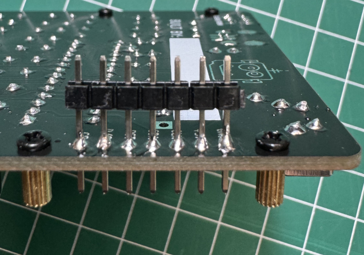
Solder the pins.
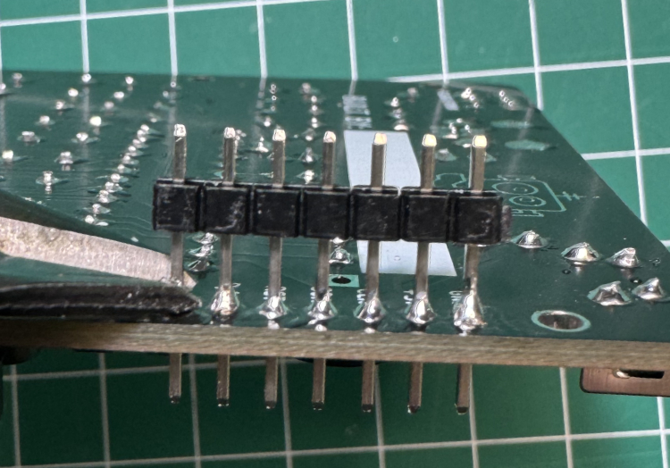
Cut the header pins as shown
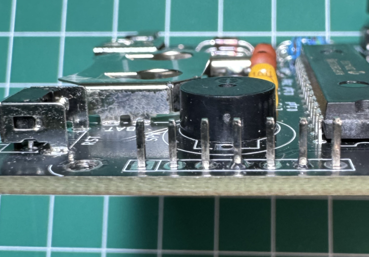
This is how it should look from the side.
Finishing the Display Male Header
Remove the four 5mm brass posts.
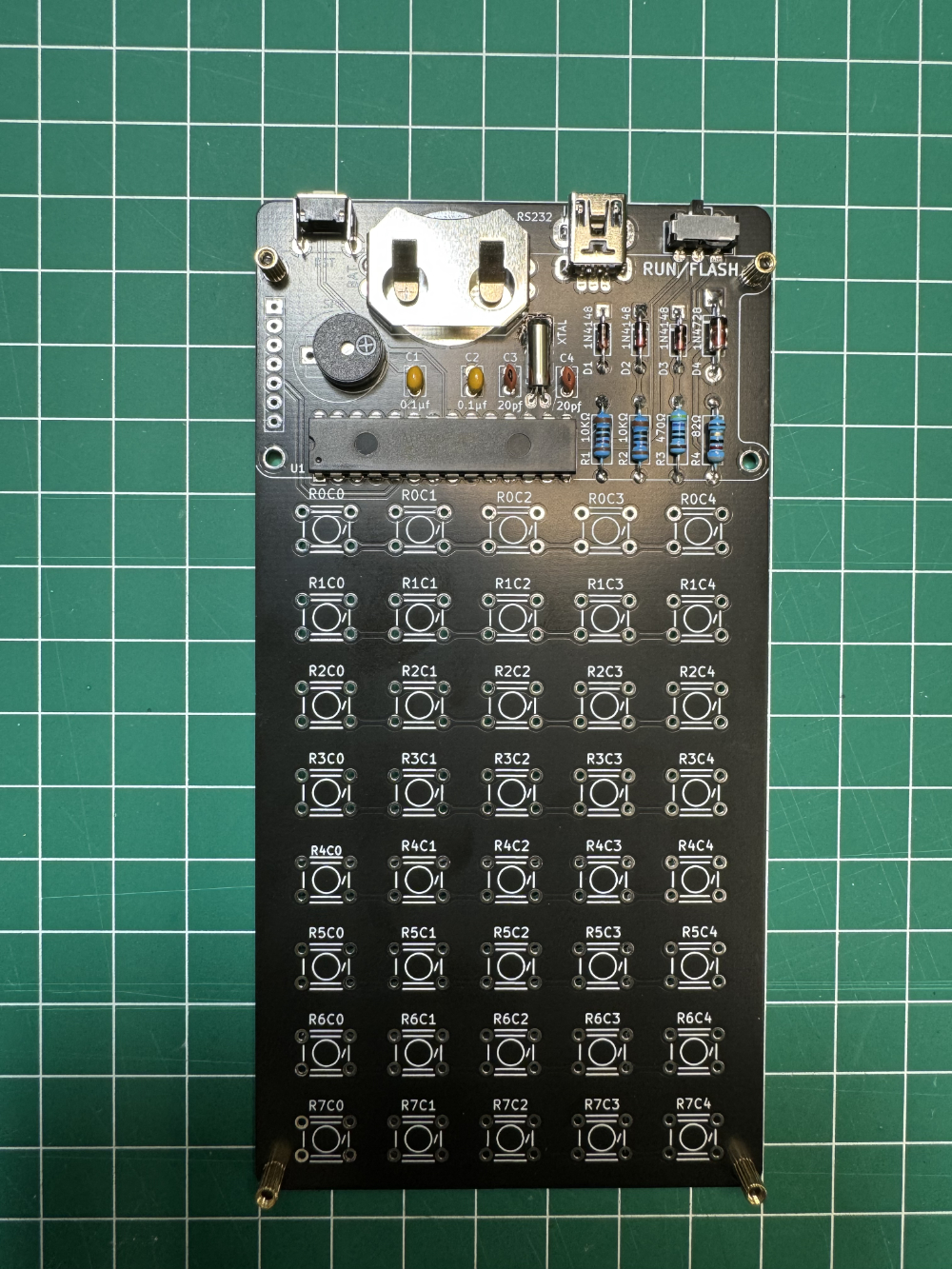
This is the final step prior to installing the tactile switces.
Tactile Switches
Start by hand tightening the four 5mm posts on the four edges of the PCB.
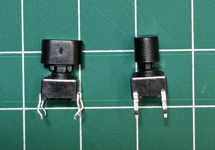
Add the keycaps to the tactile switches.
Watch the keycap orientation. Since it is dificult to remove the keycap.
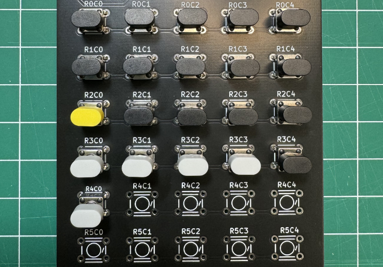
Place the switches with the keycap line by line.
Do NOT solder them yet.
Take notice of the placement of the color of the keycaps. The grey and white keycaps look the same under certain lighting.
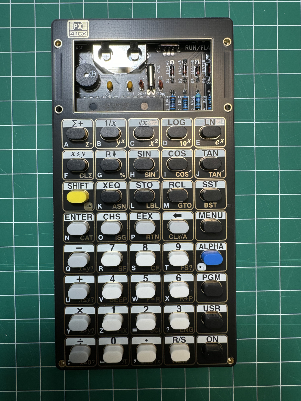
Use the top panel as a guide.
That way the buttons won’t move.
Make sure the buttons are flush with the PCB.
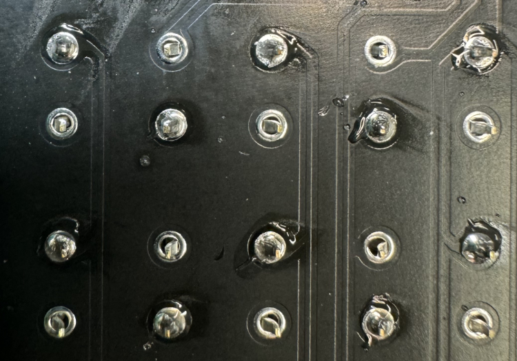
With the buttons firmly flush, it’s time to solder them.
Only solder two diagonal pines of each button. That way it would be easier to adjust if the switches turn out to be offset.
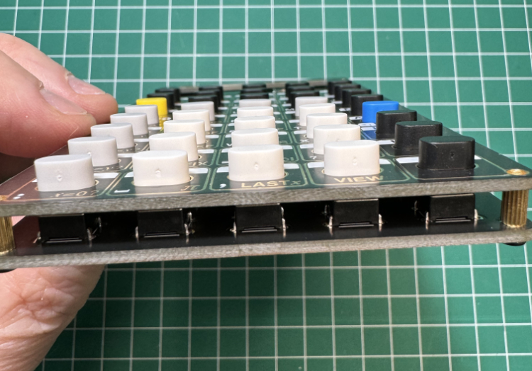
Check from bottom view to see that all buttons are straight.
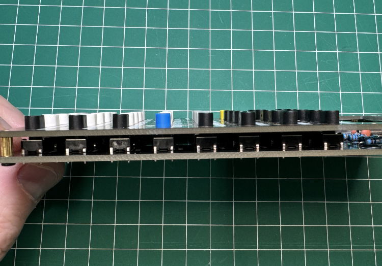
Check from side view to see that all buttons are straight.
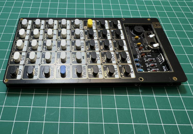
If everything looks fine, continue to solder the rest of the switch pins.
Remove the top panel and the brass posts.
Back Panel
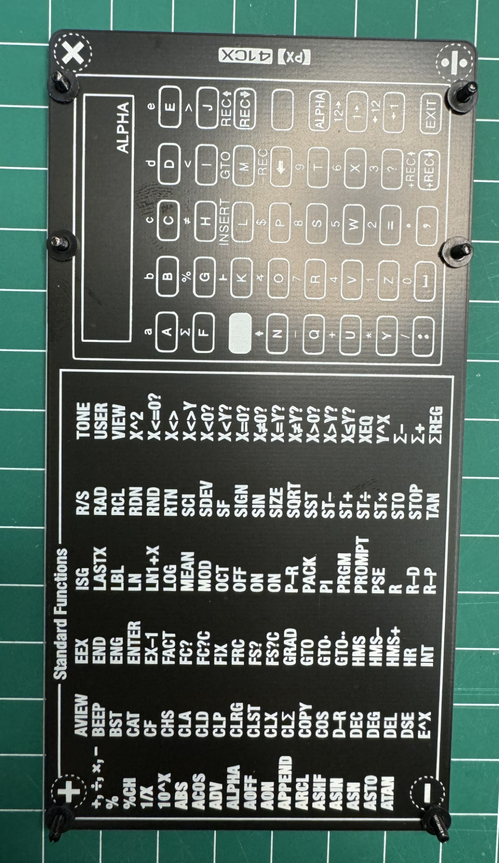
The back panel is reversible, so select the side that you like best.
Insert the six 7mm M2 bolts and add the 1mm nylon washer.
*NOTE: If you intend to install the 3D printed side bumper go to Install Bumper below.
PCB
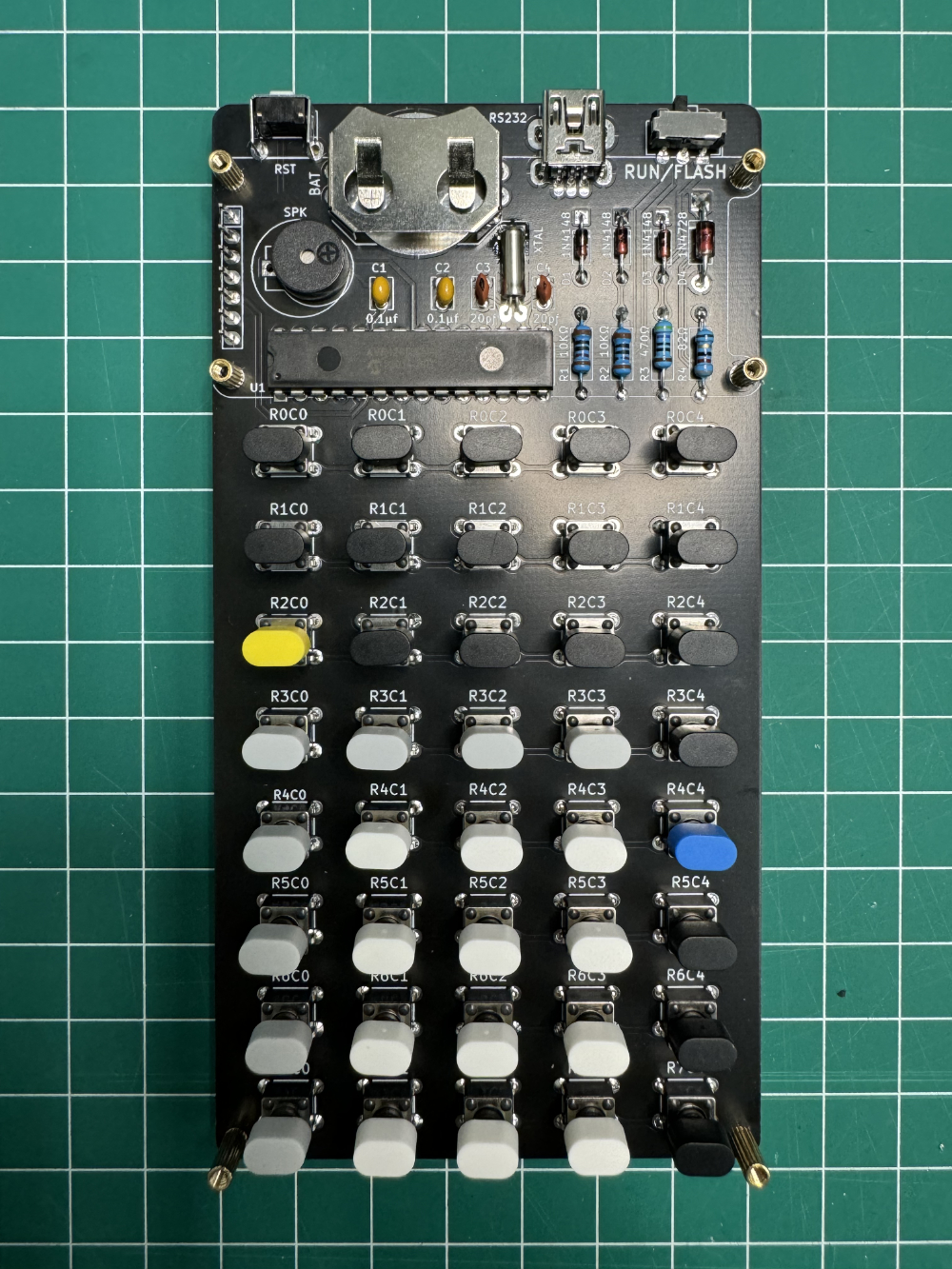
Place the PCB on top of the back panel.
Screw the brass posts.
Use the 5mm brass post for the Display module and the 7mm brass posts for the bottom.
Display
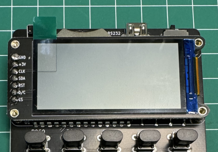
Set the Display Module.
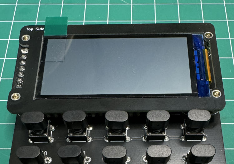
Display Bezel
Place the display Bezel with the legend “Top Side” on the top left.
Top Panel
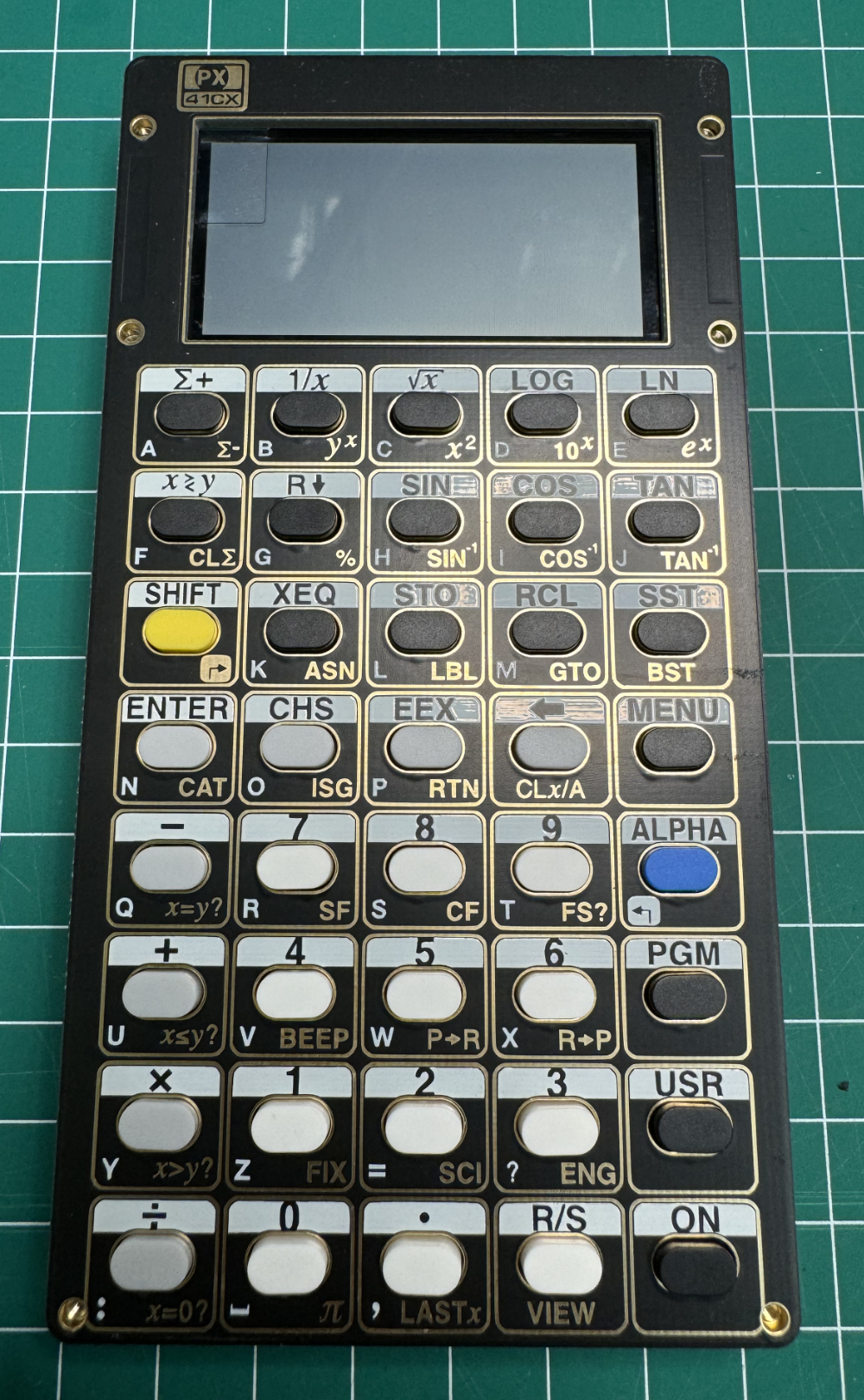
Check that the top panel sits firmly on top of the brass posts.
You might need to wiggle the keycaps.
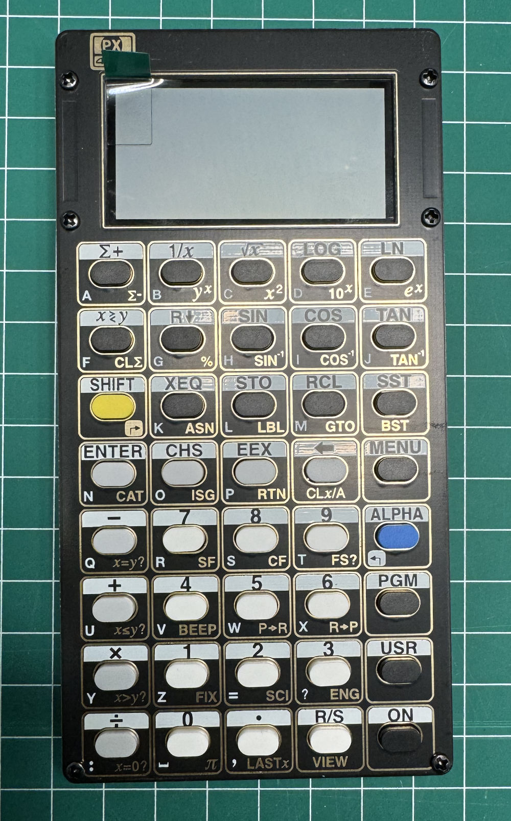
Screw Top Panel
Screw the top panel with the 6mm M2 bolts.
And your done.
3D Printed Bumper (Step 1)
Prior to assembly, remove any debris or supports left from the 3D printer.
Place the PCB inside the bumper, notice the 2 wedges on each side that need to be pushed.
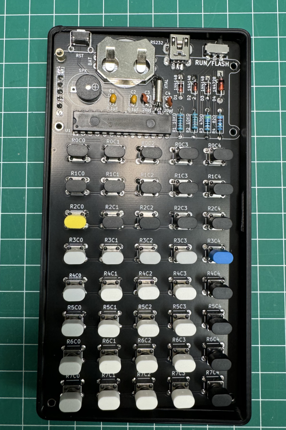
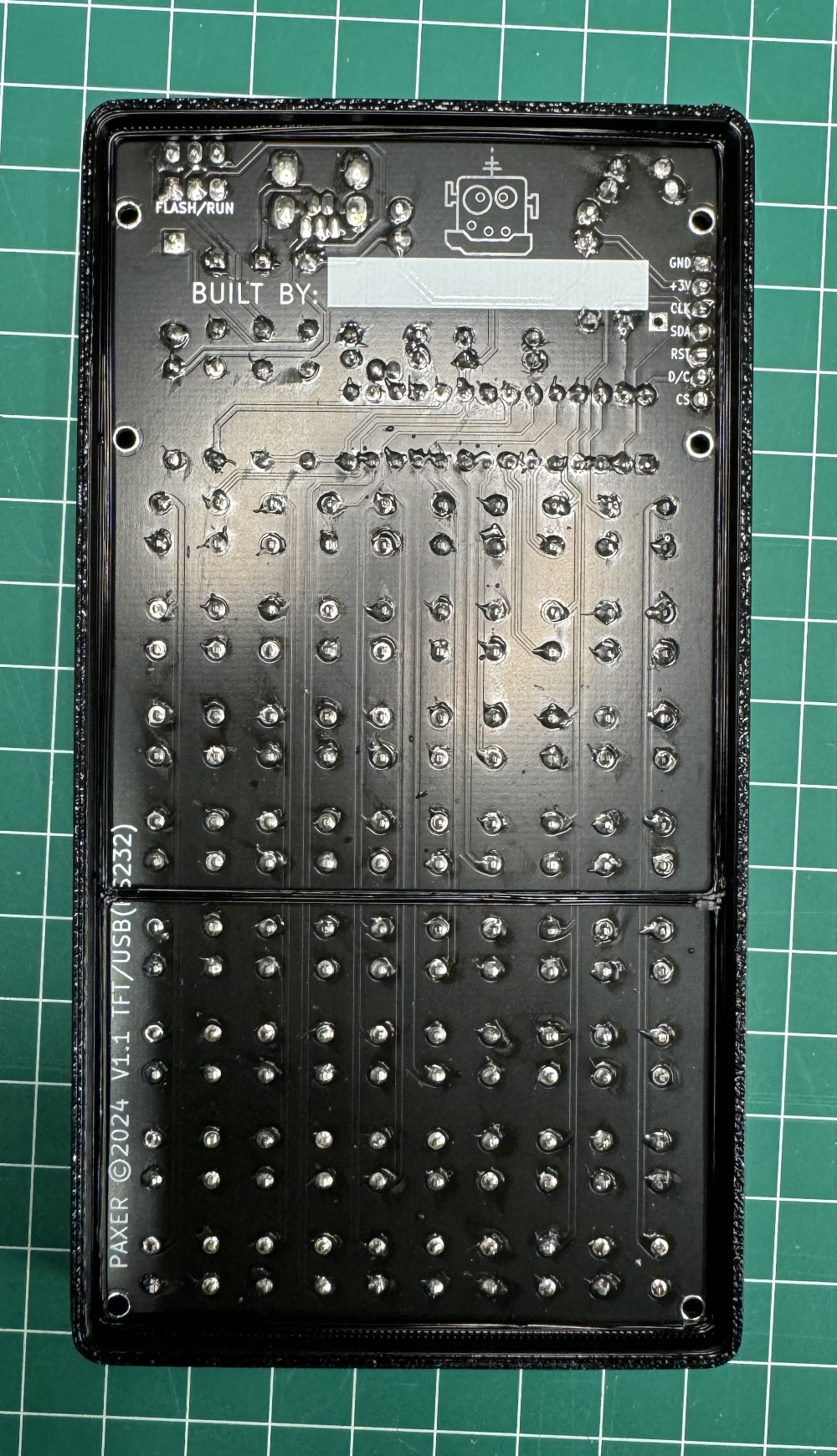
Back View (Step 1b)
The PCB should sit firmly on the inside rail.
3D Printed Bumper (Step 2)
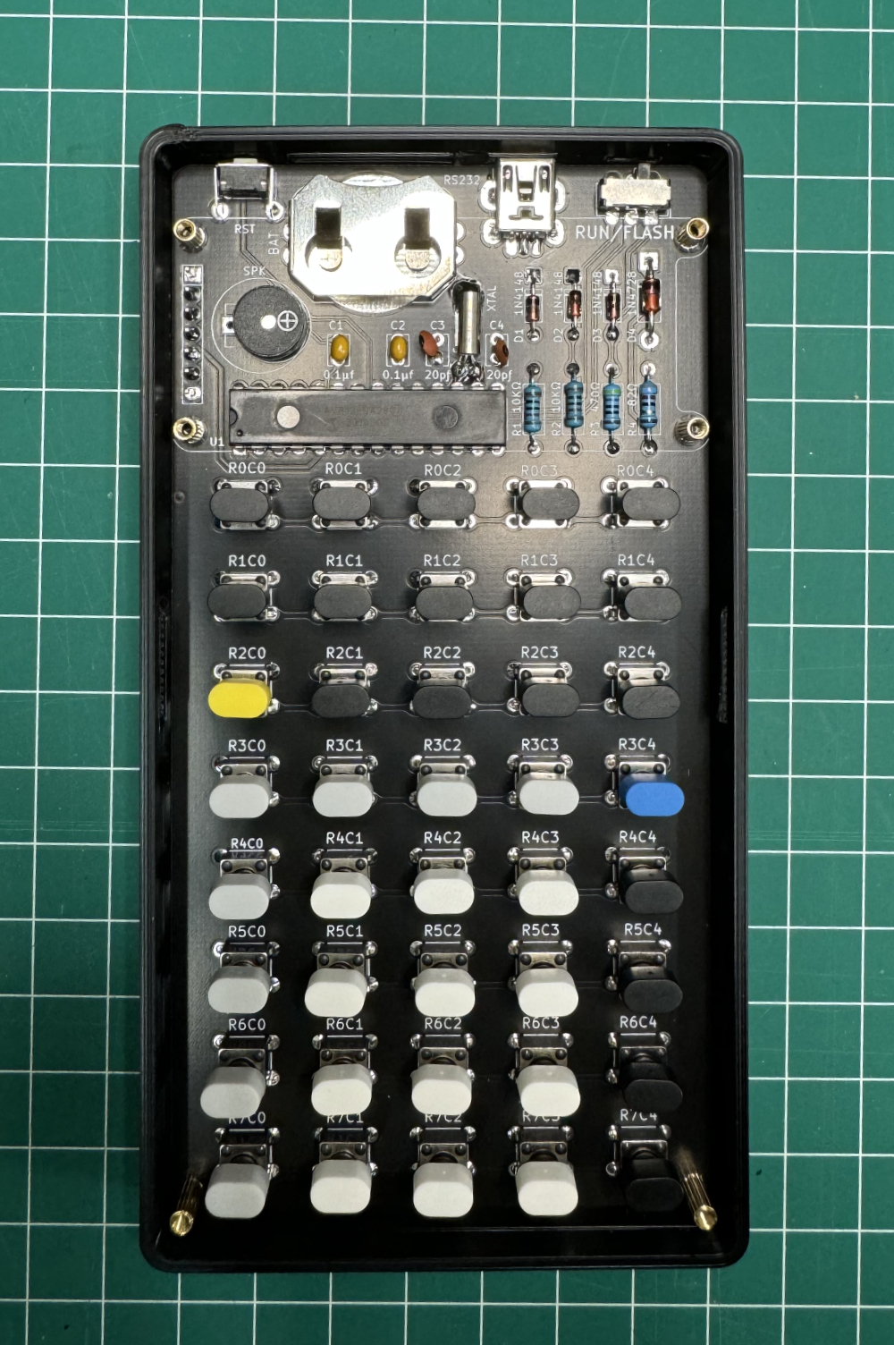
Place the back panel. The back panel is revisable, so choose the side you like.
Use the 7mm bolts to attach the back panel with PCB.
Use the four 5mm brass posts for the display (top 4).
And use the two 7mm brass posts for the bottom
NOTE: The nylon washers are not used.
3D Printed Bumper (Step 3)
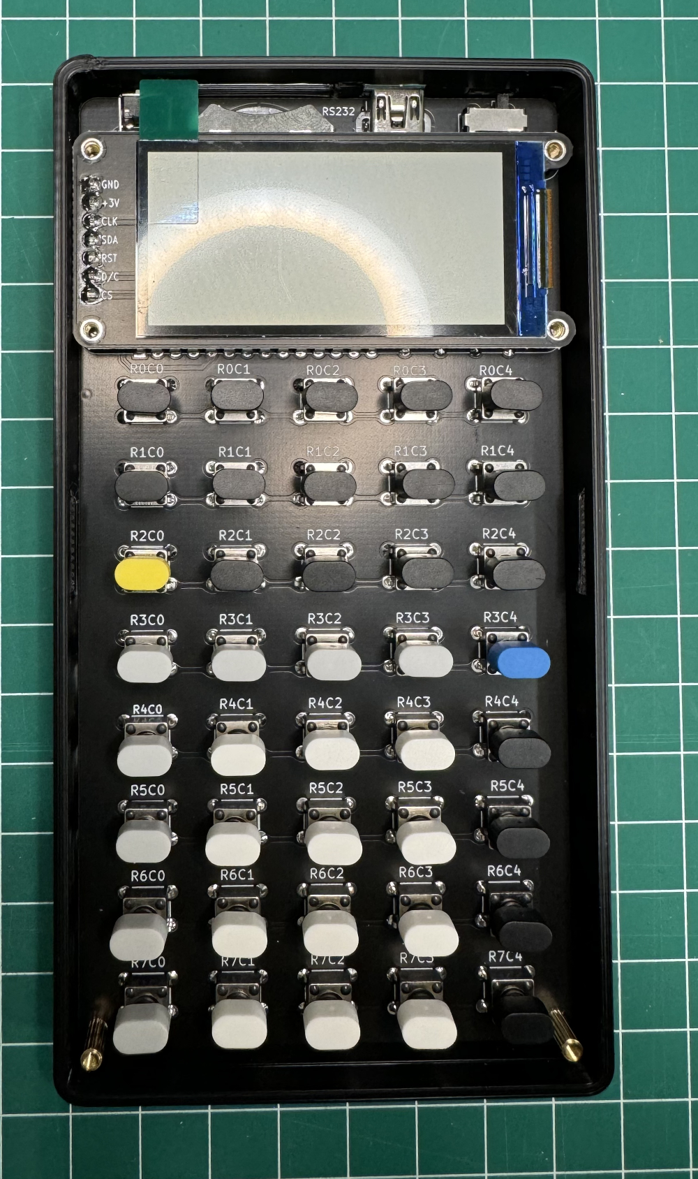
Place the Display module by carefully aligning the header connector and the four holes.
3D Printed Bumper (Step 4)
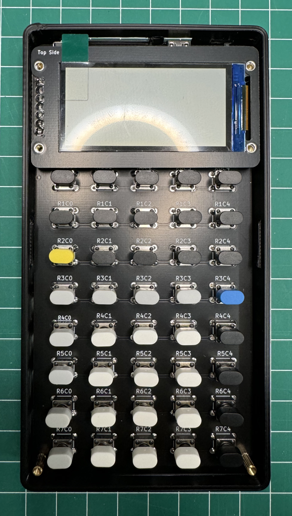
Place the display bezzel.
Make sure the “Top Side” legend is at the top left. As seen on the photo.
WARNING: If the bezzel is not seated correctly, you might crack the display when srewing the top panel.
3D Printed Bumper (Step 5)
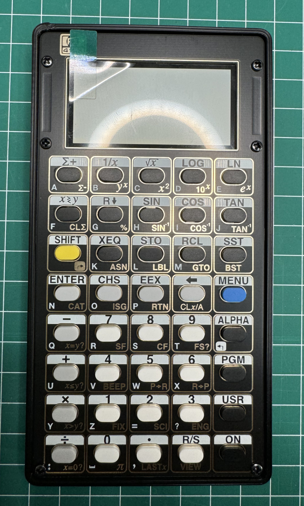
Place the top panel.
The top panel is reversable, choose the side you like.
Use the six M2 6mm bolts to secure the top panel.
Jiggle the top panel until you get the buttons trough. Do not force it.
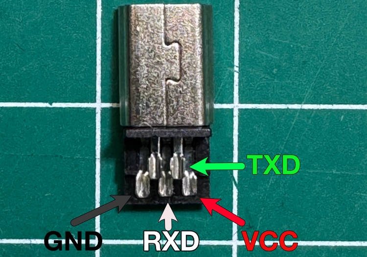
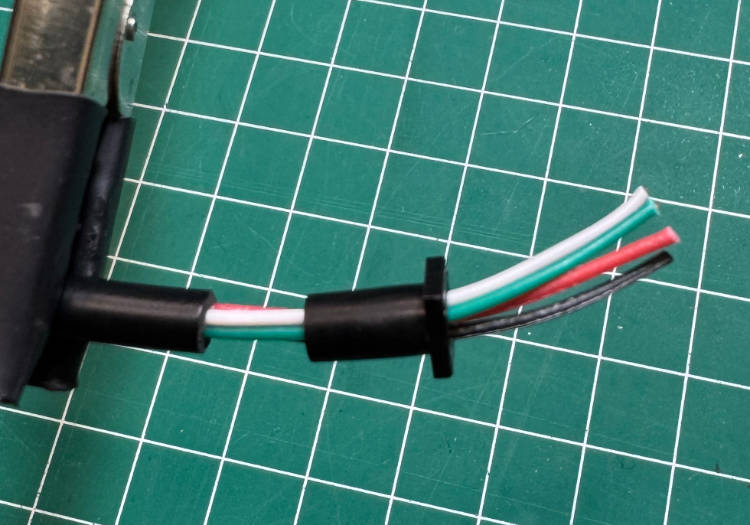
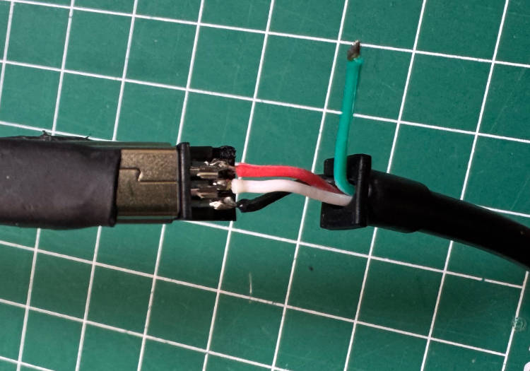
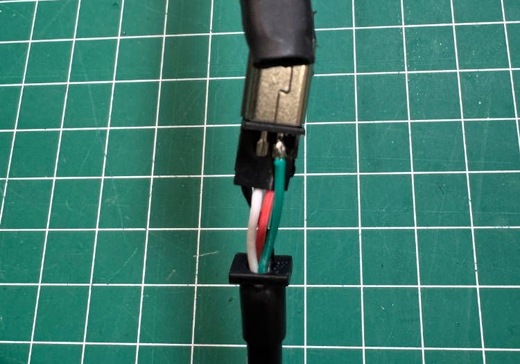
USB to Serial Cable
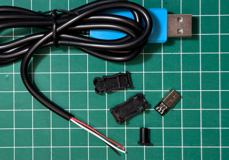
USB-Mini b to RS232
These are the parts needed to assemble the cable.
Optional:
Silicone feet.
On the back of the PX-41CX, you'll find four circles, each marked with one of the basic arithmetic operators. These are the designated spots for placing the silicone feet.
Black Bezel:
To enhance the display area, use a black permanent marker, like a Sharpie, to color the inside edge of the top panel where the display is viewed.
