Let's begin:
Step 1.0
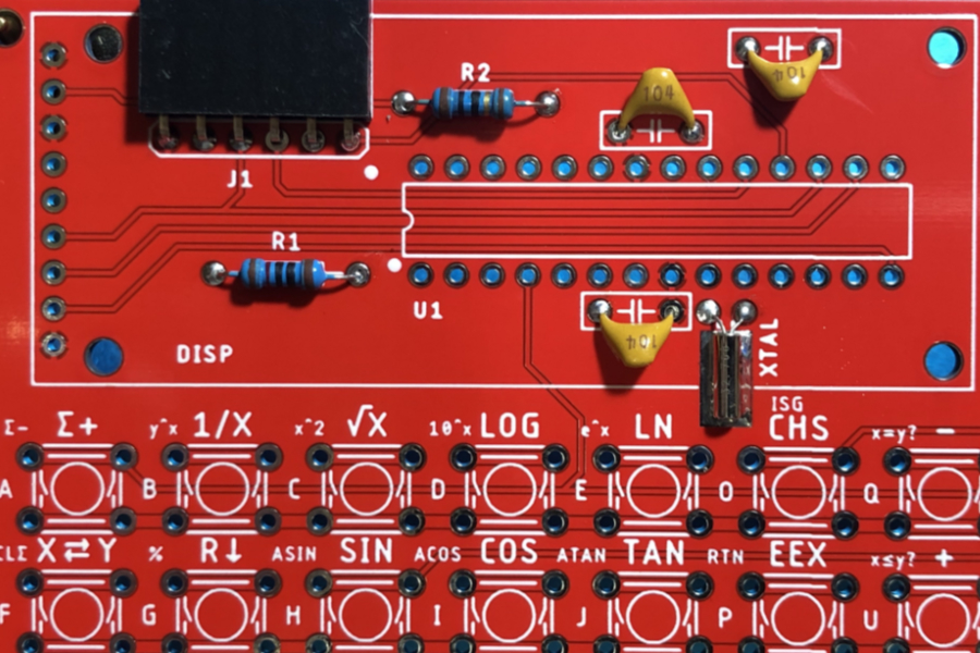
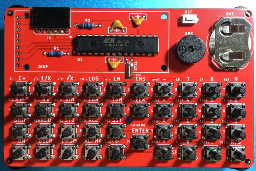
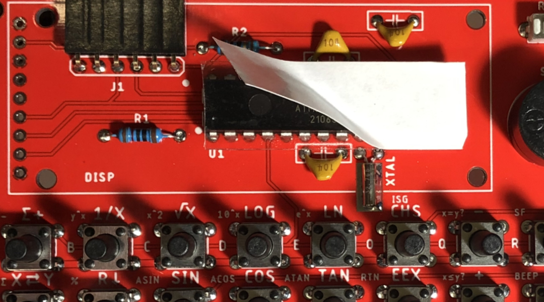
Start by soldering the shortest components.
- Resistors R1 and R2
- Capacitors C1, C2 and C3
- Programing header J1
- 32.768KH Crystal XTAL
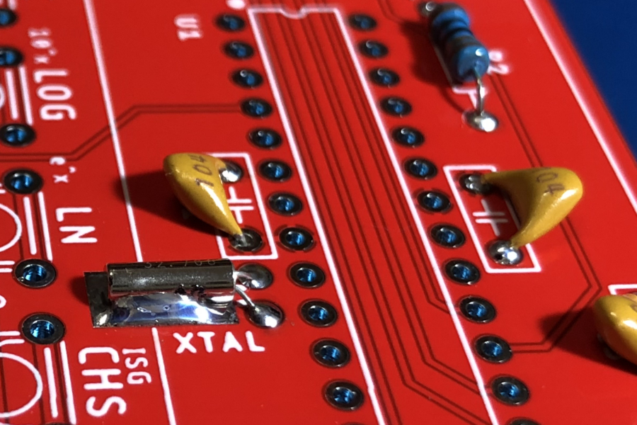
Step 1.1
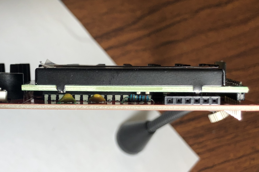
- If the capacitors are too tall, they might not allow the display to sit evenly on top of the microcontroller, so bend them slightly to one side.
- It is good practice to solder the crystal can to the PCB.
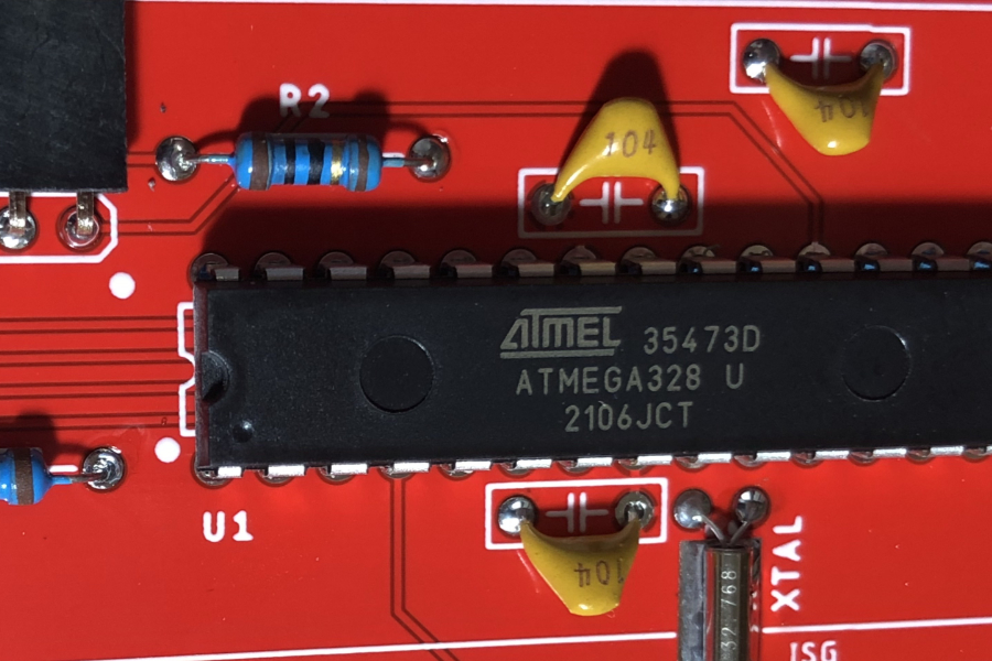
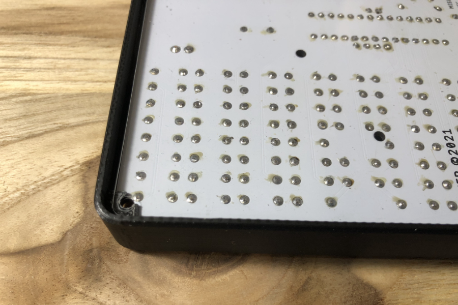
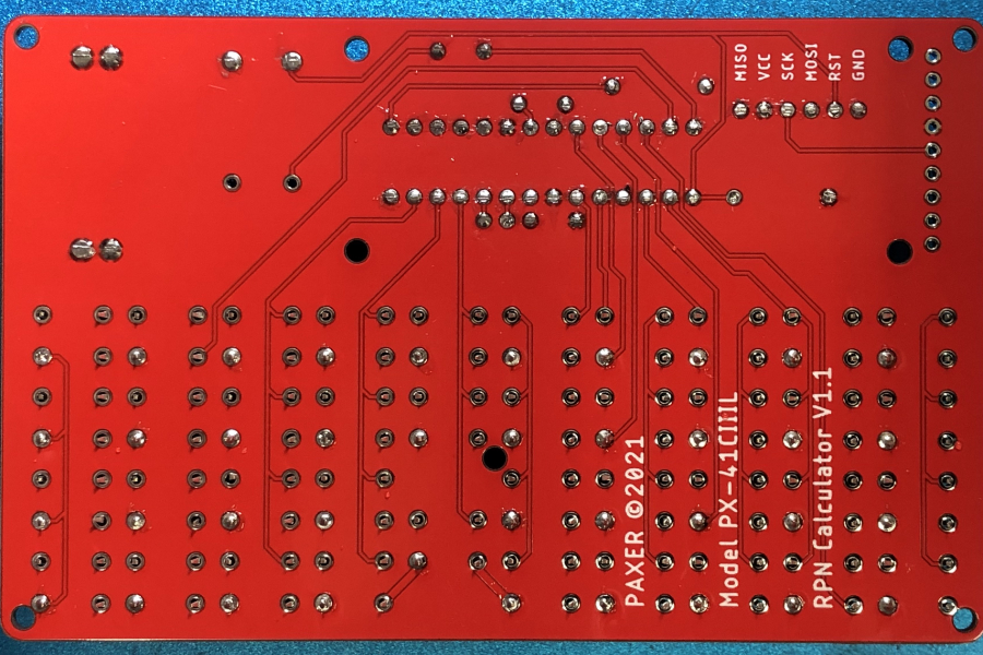
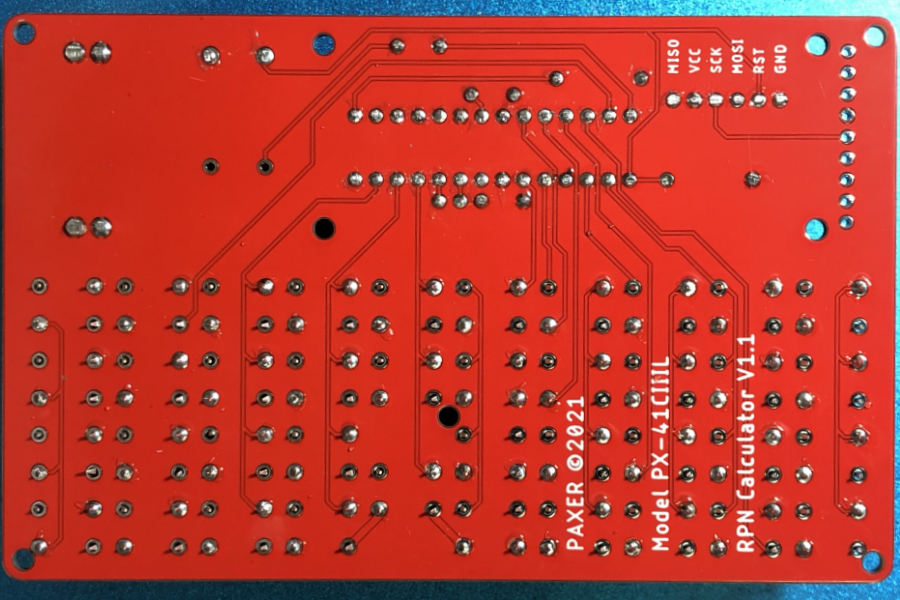
Step 2.0
- Set the microcontroller completely flush against the board.
- Make sure the microcontroller notch or dot (pin 1) is aligned with the pcb markings.
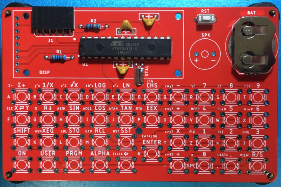
Step 3.0
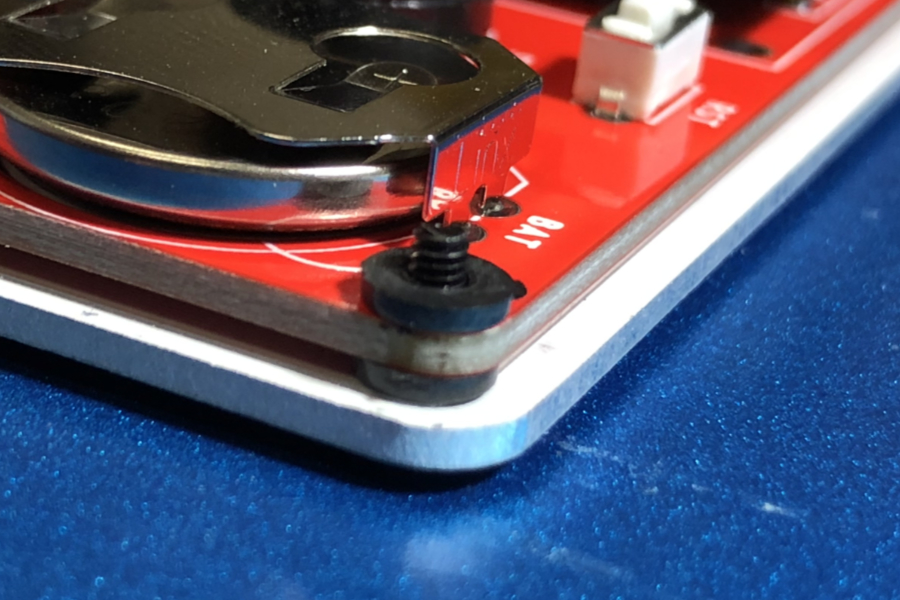
- Solder the rest switch. RST
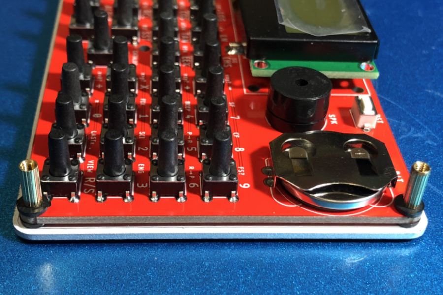
- Solder the CR2032 Battery holder.
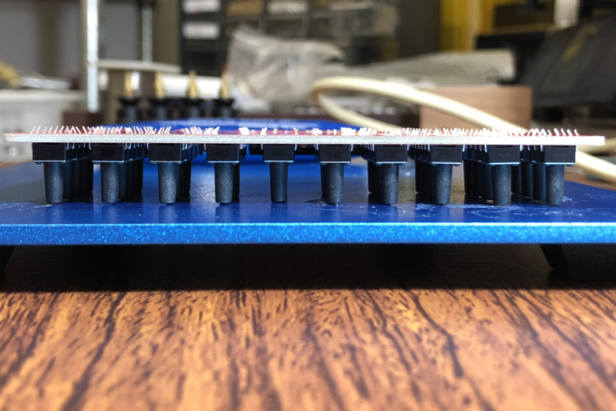
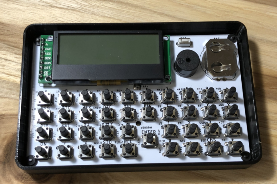
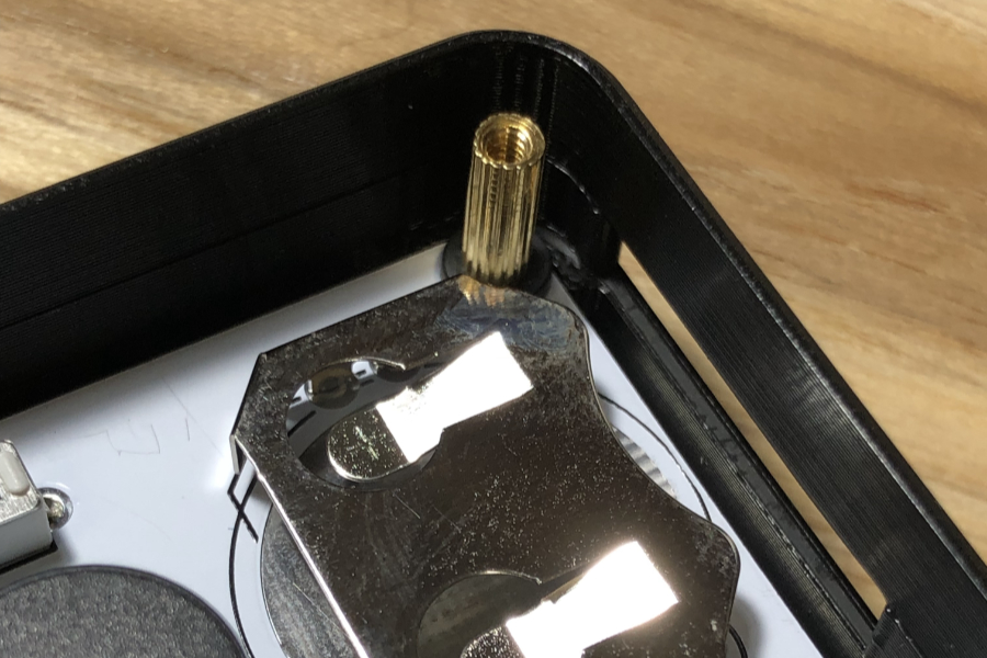
Step 4.0
- It is easier if you mount all switches on the pcb all at once then flip over the pcb and place it on a even surface.
- Push on the back of the pcb to force all switches even.
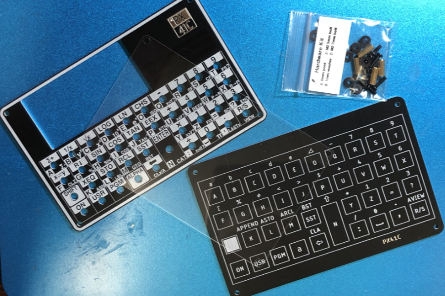
- (Some people find it easier to use the top aluminum panel as a guide.)
Step 4.1
- Solder only one pin of each switch
- Push on the back of the pcb to force all switches even.
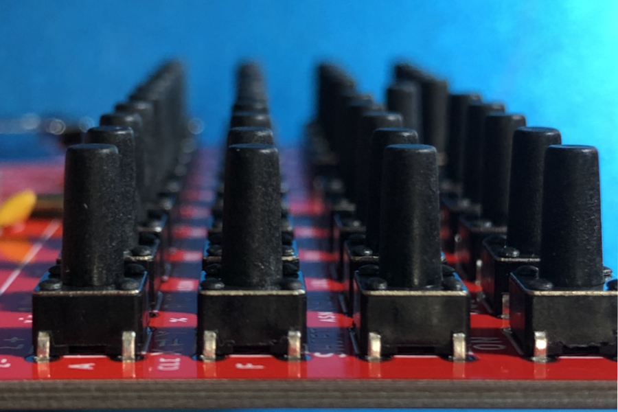
Step 4.2
- Visually inspect that the buttons are completely straight and flush to the pcb.
Step 4.3
- Solder a second pin of each button.
- Visually inspect that the buttons are completely straight and flush to the pcb.
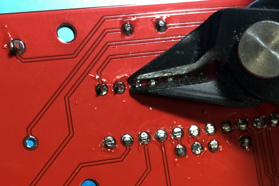
- Continue to solder all oins on the buttons.
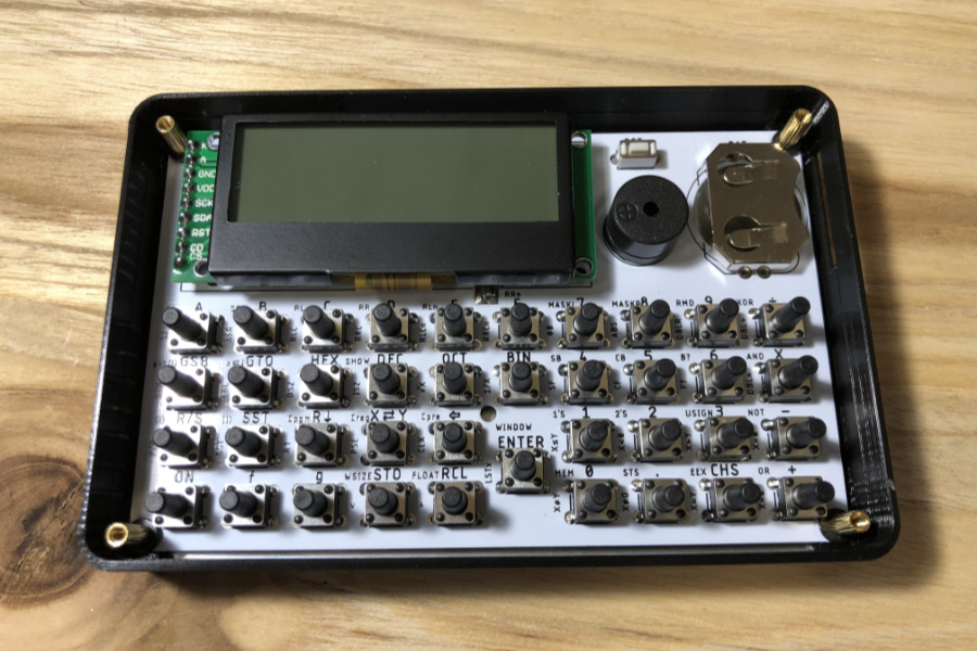
Step 5.0
- Next thing to solder is the speaker.
- Watch the polarity.
Step 6.0
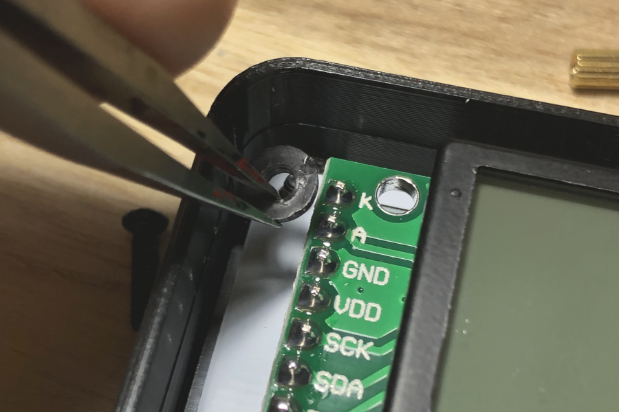
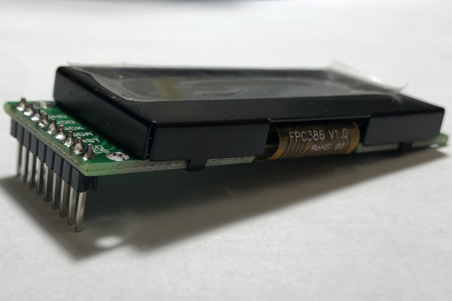
- Solder the 9 pin male header to the display.
- Make sure the header is solder to the display with the short side, flush and at a right angle.
Step 6.1
- Place a strip of double sided tape on top of the microcontroller.
Step 6.2
- Place the display directly on top the the microcontroller.
- Make sure it is sitting straight and flush to the microcontroller.
- Once you are sure is it properly sitted, continue to solder the display to the pcb.
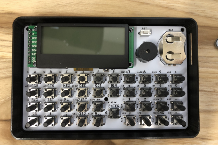
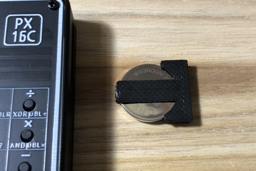
Step 7.0
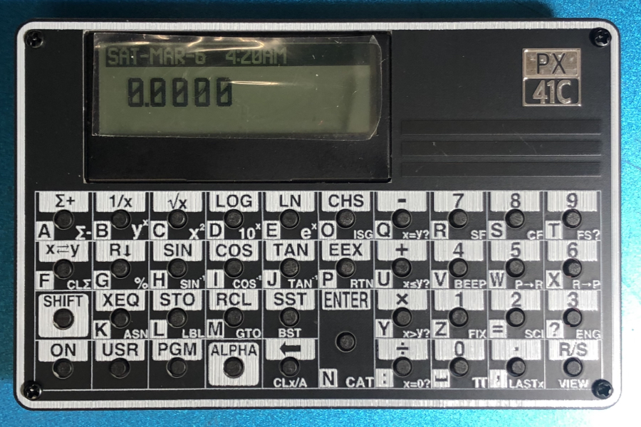
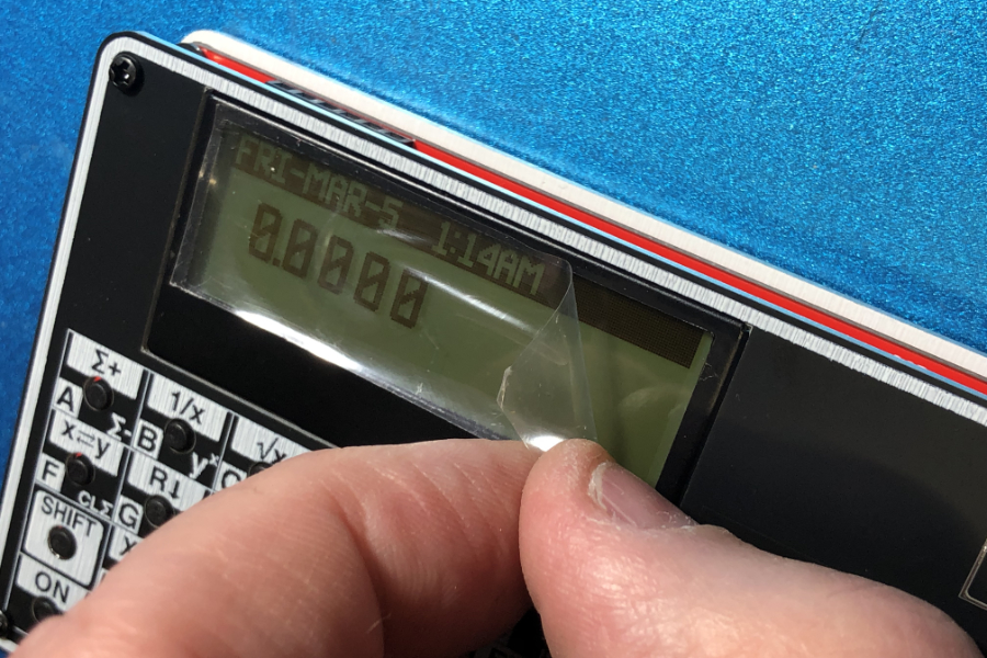
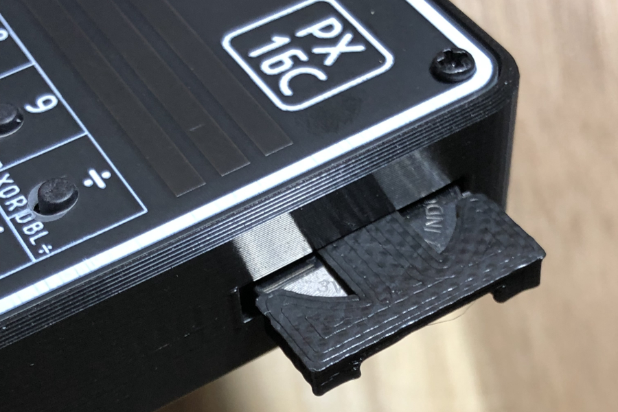
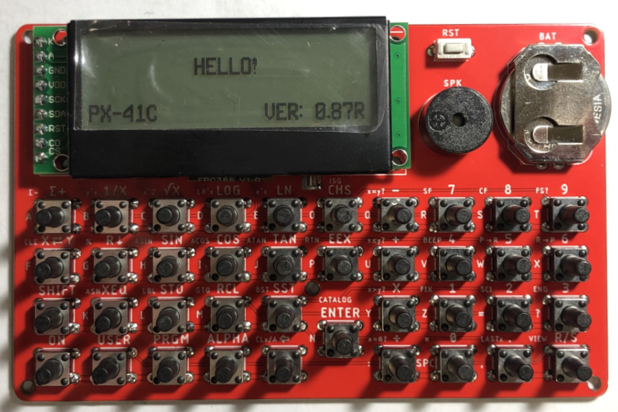
- Now it's time to test it.
-
Insert a 3V CR2032 coin battery.
Make sure the positive side of the battery is facing up. - You should be greeted with a HELLO.